


The term “Balance of Plant” points to the numerous supporting and auxiliary components of a power plant system that are necessary to create energy. BoP systems offer the necessary assistance to keep the plant functioning smoothly. Inverters, transformers, switchgear, circuit breakers, and other balance of plant components are vital, as are turbines, power generators, and other major power producing equipment. Both electrical and mechanical elements make up a BoP power plant system. Let’s look at the Electrical BoP more in depth.
The electrical components contained at the substation are mostly used to help with the windfarm’s operational characteristics. Switchgear, power protection systems, and the electric metre are commonly included in this category. A transformer may be included in the substation components to allow for power output step up or down. The size of these pieces is determined by the capacity of the windfarm
Once the project capacity is decided the PSS (Pooling Substation), USS (Unit Substation), 33kV Collector network and EHV (Extra High Voltage) Line design will take place suitably.
The standard voltage ratings of PSS are designed as 220kV/33kV, 132kV/33kV, 110kV/33kV and 66kV/33kV.
A close-coupled assembly containing enclosed main high-voltage equipment, a three-phase power transformer, and enclosed secondary medium-voltage equipment is known as a unit substation
A Compact Secondary Substation (CSS) is a type-tested and arc-tested installation that includes a switchgear enclosure, distribution transformers, low voltage (LV) switchboards, connectors, and ancillary equipment for supplying LV energy from MV systems.
The wind farm substation receives the power generated by each turbine. This is accomplished by the use of a medium-voltage collector network (Overhead Line) that connects each turbine to the substation (11-36kV). Overhead and subterranean trenched cabling can be used for connectivity, however overhead lines are the most prevalent. The entire cable length is determined by the distance between the turbines and the substation, as well as the network structure. The length of overhead wire per turbine is around 1.5 to 2.0 kilometers as a rule of thumb.
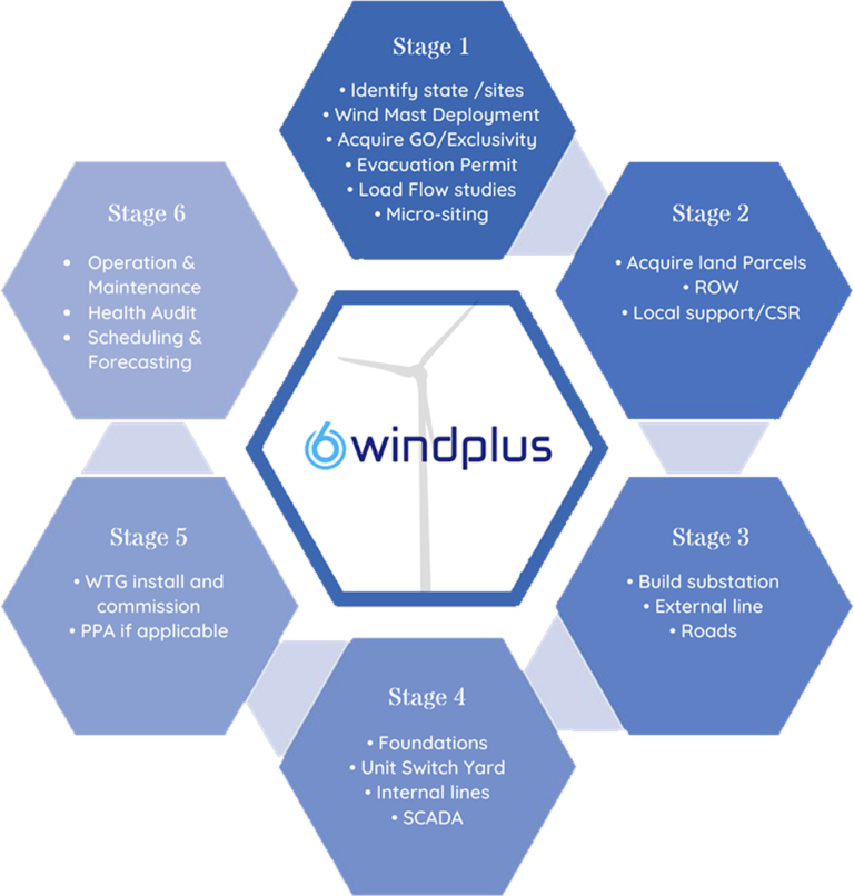
Windplus’s Mission is to provide World Class EPC of BOP(Balance of Plant) Services to the Renewable Energy Industry.
Through the six stages, influencing the global market to become a prominent & integral service provider of Renewable Energy.
Overview:
This module is designed to train engineering students from academic institutions. And in this module, we will cover all the fundamental information pertaining to the wind energy sector as shown below.
Topics Covered:
Introduction to wind energy.
Overview of wind turbine components.
Unit Substation.
Internal Lines and Pooling substation.
External Lines.
Installation and Commissioning.
Safety measures in wind projects.
Load Curtailment.
Operation and maintenance in wind farms.
Evaluation:
Evaluation should always be a part of training. So, as part of the evaluation process, we will conduct tests and assign projects to students at the end of each session. Also, certificates will be given to students at the end of the programme.
Takeaway:
Trainees will be introduced to the wind energy. Later on they will gain the knowledge about the energy conversion technique followed in the wind turbine. They are given a brief introduction on types of transformers and substations available and detailed knowledge about the electrical balance of plant.
Overview:
This module is designed to train employees and staffs from the Engineering Procurement and Construction industry. And in this module also, we will cover all the technical aspects related to wind energy sector in detail as shown below.
Topics Covered:
Basics of wind energy.
Wind Resource Assessment.
Balance of Plant – Electrical.
Balance of Plant – Civil.
Asset Management.
Commercial at a glance.
Evaluation:
Self-Assessment
Takeaway:
Trainees will be introduced to the wind energy. Later on they will gain the knowledge about the energy conversion technique followed in the wind turbine. They are given a brief introduction on balance of plant in which both electrical and civil are covered in detail. Then the technologies used for control of WTGs are explained. Commercials involved in wind power project and the performance analysis of WTG is explained in detailed.
Overview:
This module is designed to train employees and staffs from the Independent Power Producer industry. And in this module, we will cover all the technical aspects related to wind energy sector in detail as shown below.
Topics Covered:
Basics of wind energy.
Wind Resource Assessment.
Balance of Plant.
Wind turbine technology and control.
Costing at glance.
Plant Performance.
Evaluation:
Self-Assessment.
Takeaway:
Trainees will be introduced to the wind energy. Later on they will gain the knowledge about the energy conversion technique followed in the wind turbine. They are given a brief introduction on balance of plant in which both electrical and civil are covered in detail. Then the technologies used for control of WTGs are explained. Commercials involved in wind power project and the performance analysis of WTG is explained in detailed.

DIRECTOR – TRAINING & DEVELOPMENT WINDPLUS PVT LTD
Miss Mansi Yogesh Thakkar is a Leadership Trainer and a Professional speaker with 9 years of experience in training & development industry. She has completed BE.IT from Mumbai university. She is currently pursuing MA in leadership science from Chanakya International Institute of Leadership Studies , University of Mumbai.She is a dynamic young professional with training as a focal endeavor in contributing to people’s growth , personal development and organizational progress.
She is currently the Director : training & development in Windplus Pvt Ltd,Coimbatore and a Designated Partner at Mansi Thakkar Training Systems LLP , Mumbai
Her mission is to inspire all the entrepreneurs to become extraordinary leaders of tomorrow.

A Chartered Accountant by qualification, he has 30+ years cross-functional and multi-functional experience in various industries and various domains, primarily accounts, audit, commercials, legal, liaison, documentation and strategy. He is a co-promoter of Windplus and responsible for HR, IT &FINANCE functions in the company.
He has more than a decade of experience in the Windpower Industry, and was primarily instrumental in setting-up Powerica Ltd.’s Windpower Projects Development Div. which commissioned 50 MW capacity during his tenure and created a pipeline of 100 MW future capacity. He was responsible for Site Identification, Site Surveys, Land Acquisition (of govt. lands as well as private lands), acquisition of Right-Of-Way, liaison with Govt. Depts., supervising of Land Surveys, Logistic Surveys, and Power-Transmission Surveys, liaison with village-level local bodies, scrutiny of legal documentation, conceptualizing of CSR activities, liaison with OEMs and JV partners, and more. He was a member of the core-team for strategy and decision-making.
He is also a database-programmer and an Excel-guru (apart from indepth knowledge and experience in Systems Analysis and Design and Automation of manual processes), and therefore has contributed towards setting-up of IT infrastructure, systems and processes wherever he has worked.

Personal Profile:
I am in the part of Administerial work of the company. An energetic, ambitious person who has developed a mature and responsible approach to any task that undertake, or situation that am presented with. Excellent in working with others to achieve a certain objective on time and with excellence.
Strong analytic skills, used to form action plans for improvement. Enjoy challenges, problem-solving, engaging all levels of team members in improvements.
Expertise:
Employment History:
Academic Attainment:
Contact:
Phone: +91-7738356583
Email: rjk@windplus.in
Website: www.windplus.in
SF NO 1144 1B, 1A Ashoknagar, PHASE II, KALAPATTY
Coimbatore, Tamil Nadu 641048

I am passionate person when it comes to wind. A positive creative individual with a smile. To continue my career with an organization that will utilize my management, supervision & Administrative skills to benefit mutual growth and success.
Founder/Managing Director – Windplus Pvt Ltd. 2021 – Present
Sr.Vice President (Project – Wind Division) Powerica Ltd. 2016 – 2021
Executive Director, AWT Energy Pvt Ltd. / Asian Wind Tech 2005-2016
Deputy Manager – Customer Service, NEG Micon India Pvt Ltd (VESTAS). 2000-2005
Engineer – Operation & Maintenance, Windia Power Ltd (NEDWIND DK). 1995-2000
Phone: +91-7738386583
Email: windbaba@gmail.com / kmn@windplus.in
Website: www.windplus.in
SF NO 1144 1B, 1A Ashoknagar, PHASE II, KALAPATTY
Coimbatore, Tamil Nadu 641048


