A transformer is a static device that works on the principle of Faraday’s law of electromagnetic induction. A power transformer converts the voltage level of one electrical circuit to another voltage level while transferring the power in the power system network without changing its frequency (Pic.1).
Pic.1
Transformer works on the principle of mutual induction which means that when there is an alternating current flowing in a primary winding of the transformer, the magnetic flux is induced in the core in proportion to the amount of the current flowing through the primary winding. This produces a varying voltage in the secondary winding of the transformer depending on the number of coils in the secondary winding. (Pic.1)
A power transformer has two windings that are magnetically coupled through a core. The number of turns in each winding affects the voltage ratio between the primary and secondary windings. Generally, all electrical machineries work on two principles, namely the principle of self-induction and mutual induction. (Pic.2a & 2b).
Pic.2a
Pic.2b
Transformer types can be classify based on below and used as per industrial application requirement with low loss transmission & utilization.
Based on core construction
Core type (‘E I’).
Shell type ((‘L ‘L)
Core type and shell type transformers differs in their core shapes and winding arrangements. The rectangular core of a core-type transformer has two vertical limbs and a horizontal yoke. The windings are cylindrical and are placed on both limbs (Pic.3)
Pic.3
A shell-type transformer is having a central limb and two outer limbs that form a shell around the windings. The windings are inserted on central limbs and have multiple layers.
Based on voltage conversion
Step Up Transformer
Step Down Transformer
Step-up and step-down transformers are used to increase or decrease the voltage level of an AC supply. Compared to the primary winding, the secondary winding of a step-up transformer has more turns, whereas the secondary winding of a step-down transformer has less turns.(Pic.4)
Pic.4
Based on its purpose - Distribution and power transformers
A distribution transformer is used to step down the voltage for distribution to domestic or commercial users It operates most of the time at full load or nearly to full load and has resilient voltage regulation. A power transformer is used to step up or step down the voltage for transmission between generating stations and substations (Pic.5).
Pic.5
Also, there are single and three-phase types classified into distribution and power transformer types.
Based on the insulation used - Oil-cooled and dry-type transformers:
These transformers differ in their cooling methods. Mineral oil is used as a cooling medium for oil-cooled transformers, which flows through radiators or heat exchangers. Air that circulates through vents or fans are used as the cooling medium for dry-type transformers. (In below table its given type of cooling for the transformer-Pic.6a & 6b)
Pic.6a
Pic.6b
Instrument transformers
These transformers are used to measure high voltages and currents in a circuit. These types included current transformers (CT) and potential transformers (PT). Also, this type of transformer is used for the protection of the system and to avoid fire hazards during the failure of circuit instruments (Pic.7).
Pic.7
Difference between Units for Killo Volt Ampere & Killo watts
The transformer is static device and hence no rotating action inside transformer. So, there will not be rotational losses in transformer.
Iron losses and copper losses only be present during operation and due to non-available of additional losses, its phase angle between current and voltage also will not get change between input/ output power. Its power factor is self-governing of the losses.
So, output power -V*I =KVA.
Also, KVA is the unit of apparent power, Transformer is designed without considering the specify load to being connected. It can be connected with any kind of load.
So, transformer rating called in KVA.
Electrical motors are rotational equipment’s, Since its converting electrical energy to mechanical energy. Due to rotating of machinery’s fraction losses will be occur.
The power factor is fully depending on machine losses. Since phase angle between current and voltage will get change due to load of machine. So, due to variation in load (as inductive load); its power factor also will get change in results of high heating loss
So, the output power = V*I*CosΦ
Below curve explaining about phase angle difference for power factor (Pic .8)
Pic.8
Role of Power Transformer for utilization
Power transformers are one of the key components in power networks. Transformer’s main application is to step up / step down as per domestic / industrial requirements.
The service availability and durability of a transformer are the most important factors in electrical grid to sustain the reliability and transmit the power to customer from Generating station.
Pic.9a
In addition, the overall cost of the transmission line over a long period of time is significantly affected by the transformer’s reliability and productivity.
Power transformers are used to reduce the power loss caused by ohmic heating due to high current in transmission line. The distribution is the final stage in delivery of power.
The flow from power generation to consumption of the generated power is indicated in the below picture. (Pic.9a & 9b).
Windplus’s Mission is to provide World Class EPC of BOP(Balance of Plant) Services to the Renewable Energy Industry.
Our Vision
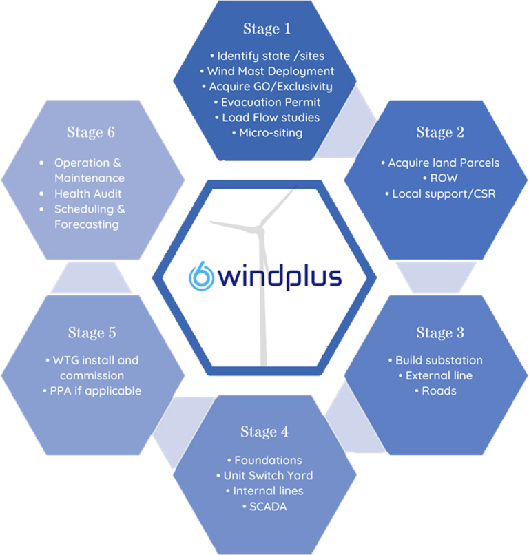
Through the six stages, influencing the global market to become a prominent & integral service provider of Renewable Energy.
Windplus Six Stages
Technical Training
Entry level training for students
Duration : 16 hours Venue : Online
Overview:
This module is designed to train engineering students from academic institutions. And in this module, we will cover all the fundamental information pertaining to the wind energy sector as shown below.
Topics Covered:
Introduction to wind energy.
Overview of wind turbine components.
Unit Substation.
Internal Lines and Pooling substation.
External Lines.
Installation and Commissioning.
Safety measures in wind projects.
Load Curtailment.
Operation and maintenance in wind farms.
Evaluation:
Evaluation should always be a part of training. So, as part of the evaluation process, we will conduct tests and assign projects to students at the end of each session. Also, certificates will be given to students at the end of the programme.
Takeaway:
Trainees will be introduced to the wind energy. Later on they will gain the knowledge about the energy conversion technique followed in the wind turbine. They are given a brief introduction on types of transformers and substations available and detailed knowledge about the electrical balance of plant.
Corporate Training for Developers
Duration : 2 days Venue : Offline
Overview:
This module is designed to train employees and staffs from the Engineering Procurement and Construction industry. And in this module also, we will cover all the technical aspects related to wind energy sector in detail as shown below.
Topics Covered:
Basics of wind energy.
Wind Resource Assessment.
Balance of Plant – Electrical.
Balance of Plant – Civil.
Asset Management.
Commercial at a glance.
Evaluation:
Self-Assessment
Takeaway:
Trainees will be introduced to the wind energy. Later on they will gain the knowledge about the energy conversion technique followed in the wind turbine. They are given a brief introduction on balance of plant in which both electrical and civil are covered in detail. Then the technologies used for control of WTGs are explained. Commercials involved in wind power project and the performance analysis of WTG is explained in detailed.
Corporate Training For IPPs
Duration : 8 Weeks Venue : Online
Overview:
This module is designed to train employees and staffs from the Independent Power Producer industry. And in this module, we will cover all the technical aspects related to wind energy sector in detail as shown below.
Topics Covered:
Basics of wind energy.
Wind Resource Assessment.
Balance of Plant.
Wind turbine technology and control.
Costing at glance.
Plant Performance.
Evaluation:
Self-Assessment.
Takeaway:
Trainees will be introduced to the wind energy. Later on they will gain the knowledge about the energy conversion technique followed in the wind turbine. They are given a brief introduction on balance of plant in which both electrical and civil are covered in detail. Then the technologies used for control of WTGs are explained. Commercials involved in wind power project and the performance analysis of WTG is explained in detailed.
Mansi Yogesh Thakkar
Mansi Yogesh Thakkar
DIRECTOR – TRAINING & DEVELOPMENT WINDPLUS PVT LTD
Profile
Miss Mansi Yogesh Thakkar is a Leadership Trainer and a Professional speaker with 9 years of experience in training & development industry. She has completed BE.IT from Mumbai university. She is currently pursuing MA in leadership science from Chanakya International Institute of Leadership Studies , University of Mumbai.She is a dynamic young professional with training as a focal endeavor in contributing to people’s growth , personal development and organizational progress.
She is currently the Director : training & development in Windplus Pvt Ltd,Coimbatore and a Designated Partner at Mansi Thakkar Training Systems LLP , Mumbai
Her mission is to inspire all the entrepreneurs to become extraordinary leaders of tomorrow.
Invite Speaker
Contact us
Bhavin Joshi
A Chartered Accountant by qualification, he has 30+ years cross-functional and multi-functional experience in various industries and various domains, primarily accounts, audit, commercials, legal, liaison, documentation and strategy. He is a co-promoter of Windplus and responsible for HR, IT &FINANCE functions in the company.
He has more than a decade of experience in the Windpower Industry, and was primarily instrumental in setting-up Powerica Ltd.’s Windpower Projects Development Div. which commissioned 50 MW capacity during his tenure and created a pipeline of 100 MW future capacity. He was responsible for Site Identification, Site Surveys, Land Acquisition (of govt. lands as well as private lands), acquisition of Right-Of-Way, liaison with Govt. Depts., supervising of Land Surveys, Logistic Surveys, and Power-Transmission Surveys, liaison with village-level local bodies, scrutiny of legal documentation, conceptualizing of CSR activities, liaison with OEMs and JV partners, and more. He was a member of the core-team for strategy and decision-making.
He is also a database-programmer and an Excel-guru (apart from indepth knowledge and experience in Systems Analysis and Design and Automation of manual processes), and therefore has contributed towards setting-up of IT infrastructure, systems and processes wherever he has worked.
Rajeswari Karunamoorthy
Personal Profile:
I am in the part of Administerial work of the company. An energetic, ambitious person who has developed a mature and responsible approach to any task that undertake, or situation that am presented with. Excellent in working with others to achieve a certain objective on time and with excellence.
Strong analytic skills, used to form action plans for improvement. Enjoy challenges, problem-solving, engaging all levels of team members in improvements.
I am passionate person when it comes to wind. A positive creative individual with a smile. To continue my career with an organization that will utilize my management, supervision & Administrative skills to benefit mutual growth and success.
Expertise
Project Development
Project Construction
Asset Management
Regulatory & Corporate Affairs
PhD in Wind energy
Employment History
Founder/Managing Director – Windplus Pvt Ltd. 2021 – Present
Administering/ Monitoring O&M activities, executed the installation, testing & commissioning of wind turbines & liaisoning work for execution of Power Evacuation Projects
Co-ordinating with NEGM Denmark for technical issues